Makerbot: Connecting the stepper motors

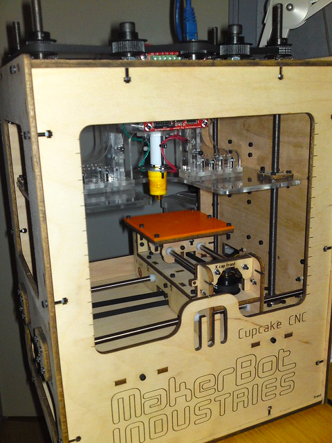
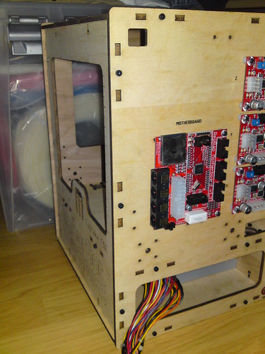
By testing the stepper motors and the heater from the ReplicatorG control panel I found I had connected the X and Y motors to the wrong controllers.

The correct way to connect them is:

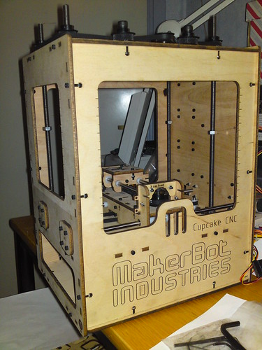
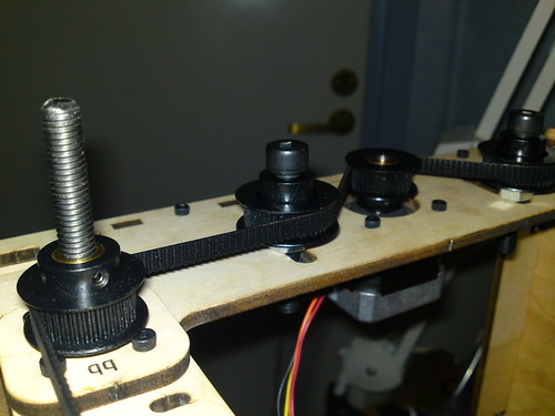
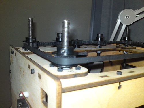
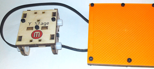
  • Z: This is the motor that is on the top of the MakerBot
  • X: This is the motor that is at bottom of the MakerBot
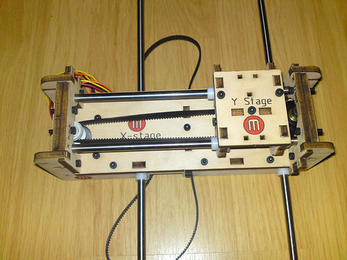
  • Y: This is the motor that is on the X-Stage (the moving table inside the MakerBot)

Cheat sheet to test them:

  • Z-: This should move the extruder down towards the build surface
  • X+: This should move the XY-Stage towards the covered side (the one where the electronics are on the other side)
  • Y-: This should move the build surface towards the M on the front

Plastruder MK4

The plastruder is possibly the most important part of the MakerBot.
This had the most pieces, the longest instruction and the most images (and it would benefit the wiki if some of the texts moved closer to the images) – but enough on that.

Hint: Twist the wires from the thermistor before cutting them to length.

Parts:


Assembly:
plastruder construction

plastruder construction

Having put the barrel back together. Hint for others, put the nut next to the PTFE heater barrier. Remove the barrier, secure the nut and then put on the Nichrome wire, it is a lot easier than the method suggested in the wiki (putting on nichrome, insulators and removing the PTFE barrier and putting in the big washer).


plastruder

Only remains to run the wires and hook them up

XY Stage Installation

The wiki says: *TIP* If the rods are too short they will move back and forth causing loss of resolution and additional noise. If this is the case for you, just insert something between the end cap and the rod to help compress it.
Well I put one of the M3 nuts in each of the two caps to press the rods into position.

Some images:

The parts needed for this laid out


xy-stage installation construction
XY stage installation

Assembled and done.

Finished assembling the X-Stage

Tips for others:

  • I thought I was smart when I got a shorter M5 for the idler pulley (I had a M5x40 that I tried to use instead of cutting the M5x45) screw (instead of cutting it down) – however it was not threaded as long as the longer screw so it didn’t fit under the X cap. If you think of using a shorter screw, verify that it will fit under the X cap.

The only problem I ran into (apart for the screw) was that when I made sure there was 1 mm clearance between the drive pulley and the motor the timing belt was not level with neither the Y-stage nor the idler pulley. I moved the drive pulley several mm’s up until it was level with the rest.
That was not a major problem as it was easy to reposition it, but it was time consuming to get the drive pulley to be 1 mm above the motor.

The parts laid out:

x-stage parts

The parts for the X-Stage laid out.
The big screw is not the right one, the small image is with the right screw (before it was cut down to size)

Some construction images:
X-Stage construction
X-Stage idler pulley

x-stage construction

The drive pulley on the motor shaft.

And the completed assembly:
x-stage complete

Finished building the Y-stage

This part was very simple and straight forward.

The only two problems I ran into while making the Y-stage was

  • That I did not know what “Flanged bearings” were – and it took me a while to find the <a href="part lists in the subversion archive. Once I had that it was simple to find a data sheet with a drawing on it.
  • [not MakerBot related] The lid for the superglue bottle had been glued to the plastic below. Had to find a Tongue-and-groove pliers to get it unstuck

Tips for other builders:

  • Try to insert the magnets from both sides before finding a small file to make the holes larger
  • If you are unsure what the part you are looking for should look like, consult the part list and the try to find a drawing of it – if you live in a country that isn’t native English speaking there is little point trying to ask others; unless they have made a MakerBot or similar before.
  • When adding the acrylic build surface to the wood start with the two screws that are diagonally to each other (if you would start with one side there is a rather large chance that the last screws won’t line up correctly) [see construction picture 3]
  • When putting in the last magnets, using a plastic plier (or some other non magnetic item) is easier than using a hex key 😉

Some images from the process:
All parts laid out before:

y-stage_parts

The flanged bearings are the white "tubes with a lip on"

Construction images:
y-stage_construction_1
y-stage_construction_2
y-stage_construction_3

Final result:
y-stage_construction_completed