Tips for others:
- I thought I was smart when I got a shorter M5 for the idler pulley (I had a M5x40 that I tried to use instead of cutting the M5x45) screw (instead of cutting it down) – however it was not threaded as long as the longer screw so it didn’t fit under the X cap. If you think of using a shorter screw, verify that it will fit under the X cap.
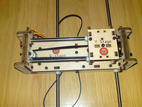
The only problem I ran into (apart for the screw) was that when I made sure there was 1 mm clearance between the drive pulley and the motor the timing belt was not level with neither the Y-stage nor the idler pulley. I moved the drive pulley several mm’s up until it was level with the rest.
That was not a major problem as it was easy to reposition it, but it was time consuming to get the drive pulley to be 1 mm above the motor.
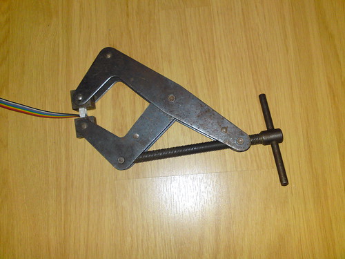
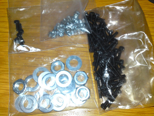
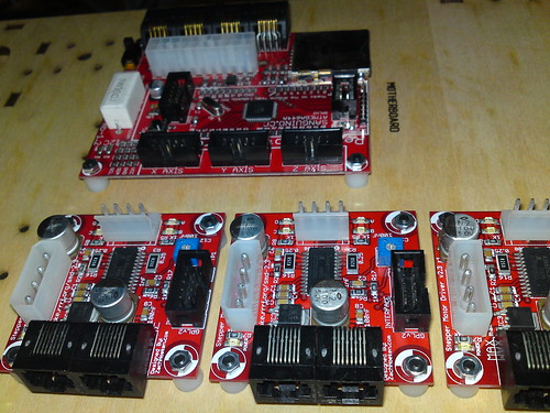
The parts laid out:
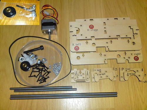
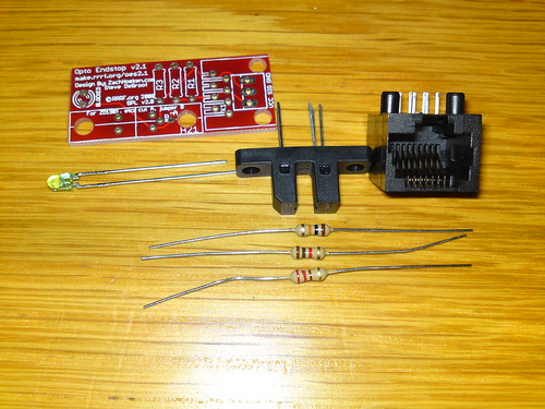
The parts for the X-Stage laid out.
The big screw is not the right one, the small image is with the right screw (before it was cut down to size)
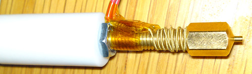
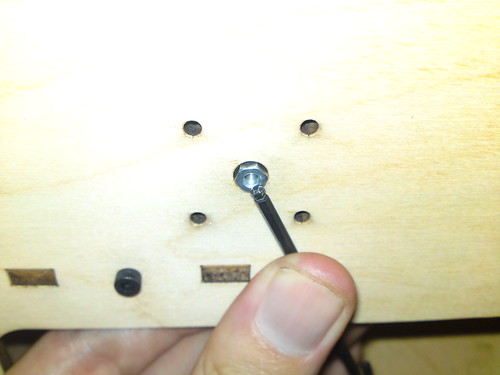
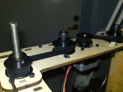
Some construction images:


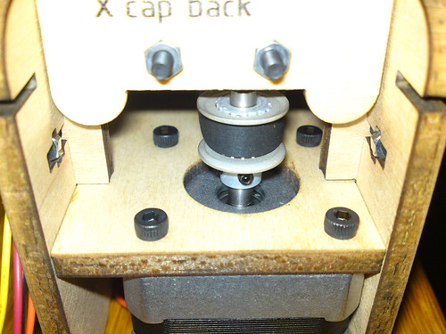
The drive pulley on the motor shaft.
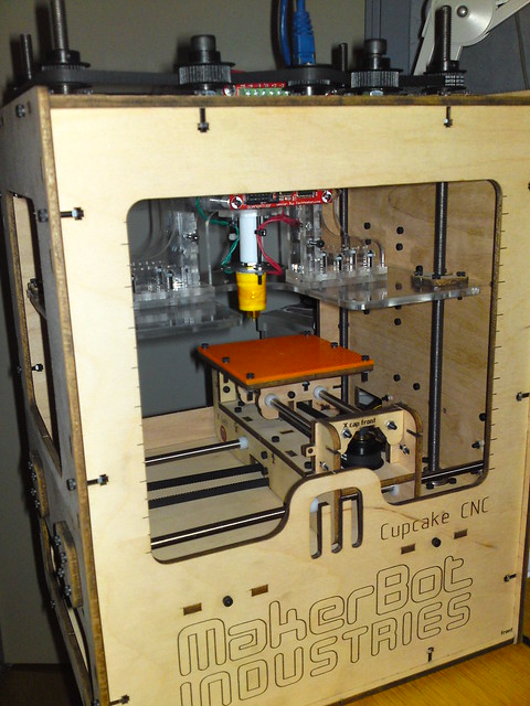
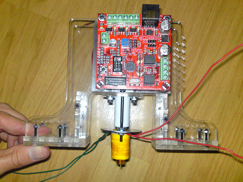
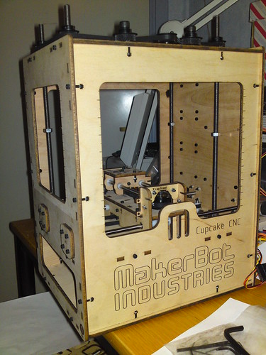
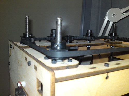
And the completed assembly: