6 opto endstops for fermat

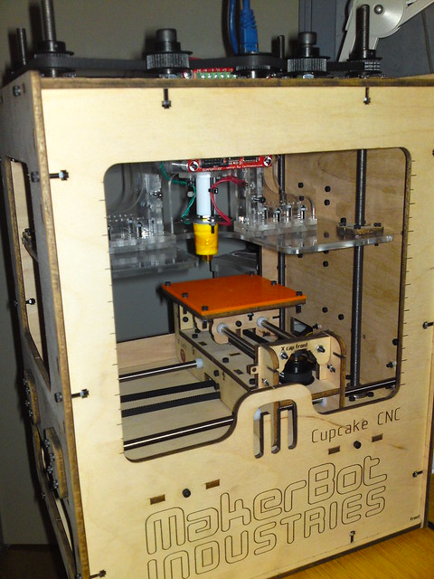
Endstops are used so that the machine using them to know where the ends of an area is. The opto endstop uses a Transmissive Opto Sensor and a flag that tells the machine that the limit is reached.

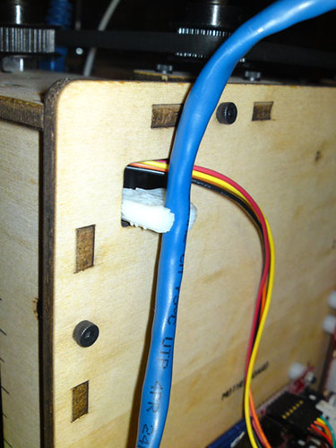
A opto endstop also needs a flag to break to break the optical sensor, but that is a later thing to do; also needs a bunch of cables for the installation…

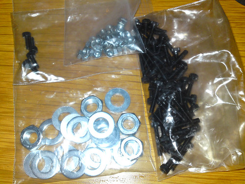
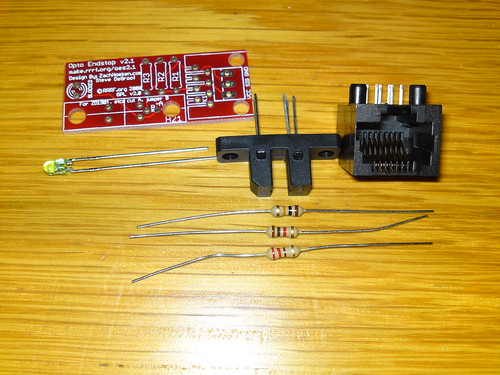
This is the components for one endstop laid out:
opto endstops kit

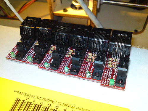
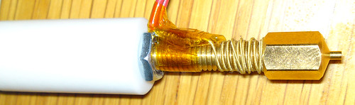
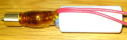
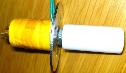
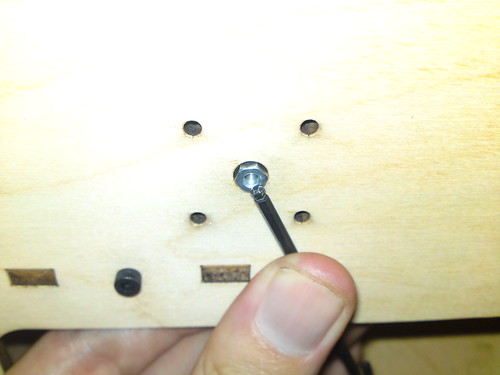
And the finished result:
6x opto endstops

Made a Makerbot extruder cable clip by justjoheinz

This is a small clip that fits in the hole above the motherboard and clips the cable that goes to the extruder – thus keeping it from touching the drive belt.

The model can be downloaded from Thingiverse to be printed.

The raft came lose at the end of the print so it was not completely finished, however it is still useful.

Makerbot extruder cable clip by justjoheinz (3989)

BECKMAN 3020 DMM – Cleaning and changing battery

I have gotten an old hand held DMM that had gotten some paint spilled on the LCD a long time ago.
Speaking of old

I have tried measuring resistance and voltage with it before but never gotten any good readings with it; the ohms was swinging between 0 and 50 when the test leads where shorted.

Today I figured I should try to clean it off as it is hard to read the LCD with paint over most of it.
I used some nail polish remover to get rid of the paint and when that was done I was able to see the decimal dot on the LCD.
Once I could see this I knew it was time to change the battery [On this DMM the decimal dot flashes when it is time to swap battery].
I am a bit surprised that the DMM even came to life, it should have a 9V battery. The old one had a best before date of 2001 and held all of 4.2 volts.

With a fresh and stronger battery the readings got a lot better, for instance with the test leads shorted now it reads about 0.2 ohms.

BECKMAN 3020

Makerbot: Connecting the stepper motors

By testing the stepper motors and the heater from the ReplicatorG control panel I found I had connected the X and Y motors to the wrong controllers.

The correct way to connect them is:

  • Z: This is the motor that is on the top of the MakerBot
  • X: This is the motor that is at bottom of the MakerBot
  • Y: This is the motor that is on the X-Stage (the moving table inside the MakerBot)

Cheat sheet to test them:

  • Z-: This should move the extruder down towards the build surface
  • X+: This should move the XY-Stage towards the covered side (the one where the electronics are on the other side)
  • Y-: This should move the build surface towards the M on the front

First challange; ReplicatorG said “Extruder board: Null version reported! Make sure the extruder is connected and the power is on”

The first challenge was that no green LED’s lit up on either the motherboard, the stepper cards nor the extruder.
All I could see was a red flashing light.

In short, don’t get confused by the error message. The power to turn on is not at the extruder, but at the motherboard.
There is a power switch on the lower left part of the motherboard – this should be turned on.

If you are getting this error when the power is turned on there, then something else is the issue 🙁

When all works well you will get a message about the motherboard version and extruder version in the text box below the main window (where the build area and model is shown)

Plastruder MK4

The plastruder is possibly the most important part of the MakerBot.
This had the most pieces, the longest instruction and the most images (and it would benefit the wiki if some of the texts moved closer to the images) – but enough on that.

Hint: Twist the wires from the thermistor before cutting them to length.

Parts:


Assembly:
plastruder construction

plastruder construction

Having put the barrel back together. Hint for others, put the nut next to the PTFE heater barrier. Remove the barrier, secure the nut and then put on the Nichrome wire, it is a lot easier than the method suggested in the wiki (putting on nichrome, insulators and removing the PTFE barrier and putting in the big washer).


plastruder

Only remains to run the wires and hook them up

XY Stage Installation

The wiki says: *TIP* If the rods are too short they will move back and forth causing loss of resolution and additional noise. If this is the case for you, just insert something between the end cap and the rod to help compress it.
Well I put one of the M3 nuts in each of the two caps to press the rods into position.

Some images:

The parts needed for this laid out


xy-stage installation construction
XY stage installation

Assembled and done.